

Micromagnetic calculations of samples with arbitrary geometries or irregular microstructures are efficiently made using finite element methods (FEM). The accuracy of its solutions depends on the discretization of the sample in space. In hard magnetic materials the magnetization is uniform within magnetic domains whereas it is highly non-uniform in domain walls, near nucleation sites, vortices or grain boundaries. Rave has shown that the discretization length has to be comparable to the exchange length [1]. It is desirable to adapt the finite element mesh to the solution and optimize the number of unknowns. As domain walls can move due to external fields the discretization has to be adjusted at run-time. The nucleation and expansion of reverse domains is also made easier by a finer mesh.
This paper introduces a new method for adaptive refinement and coarsening in micromagnetic finite element calculations. In our 3D simulation we use a magnetic scalar potential to treat the long-range demagnetizing fields. For its calculations a hybrid finite element / boundary element method is applied. The time evolution of the magnetization follows from the integration of the Gilbert equation of motion with critical damping (alpha=1). The discretization and time integration error can be estimated during the calculations and used as an indicator for areas which need to be refined. A very efficient refinement strategy for tetrahedral meshes has been described by Bey [2].
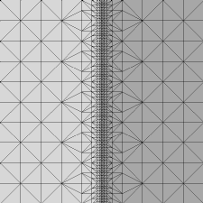
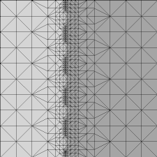
The top left plot in fig. 1 gives the initial mesh of a Nd2Fe14B platelet with an extension of 200 nm and a thickness of 20 nm. The mesh has been refined around the domain wall. After calculation of the equilibrium state for zero applied field the domain wall starts to move under the influence of an applied field of 0.1 times the anisotropy field. The wall collapses as it reaches the elements of the coarse mesh leading to antiparallel magnetization vectors at the nodes of a common edge [3]. This structure remains stable because there is no torque on the magnetization. The local refinement of the finite element mesh inserts new nodes within the domain wall and the wall can be resolved on a smaller length scale. Coarsening of the mesh at the former wall position keeps the total number of finite elements constant.
After insertion of new elements and nodes the magnetization can be interpolated linearly between the values of the neighboring nodes and normalized. The torque acting on the magnetization in a narrow band enclosing the new nodes will be considerably higher than the torque on the remainder of the mesh. Thus, we propose to relax the magnetization of the new nodes using a submesh containing only elements in a narrow band around the new nodes. This technique is called windowing [4, 5]. In numerical micromagnetics a similar approach has been proposed by Lewis and Della Torre [6]. The Gilbert equation is solved within the computational window. At the boundary Dirichlet conditions for the magnetization are applied. Since magnetostatic interactions are long-range the scalar potential is determined on the entire mesh, with the magnetization kept fixed outside the narrow band. Under the influence of an applied field the domain wall moves. Again a narrow band technique can be applied to keep track of the domain wall position. The top right mesh in fig. 1 shows the computational window. After several time steps on this narrow band, a few integration steps are performed on the entire grid, in order to account for minor changes of the magnetization within the domains. Then a new computational window, which follows the movement of the wall, is determined. At the bottom of fig. 1 the finite element mesh after four refinement and coarsening steps is given. The result clearly shows that the high density region of the mesh moves together with the domain wall. Simulations using a uniform mesh with the same minimum element size would exceed the capabilities of our workstations by far.
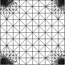
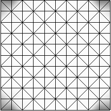
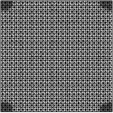
Mesh 1 in fig. 2 is the initial mesh of a Nd2Fe14B platelet with an extension of 200 nm and a thickness of 8 nm. Nucleation of reverse domains starts in the corners of the platelet. Three refinement steps lead to mesh 2. The coercive field has been calculated for the coarse (mesh 1), the refined (mesh 2) and the fine uniform mesh (mesh 3). Table 1 compares the three FE-meshes and the results obtained from the simulations. The smallest element length of mesh 2 is 2.5 nm which is approximately half the domain wall width. Yet, it contains less than half the number of elements of mesh 3. The minimum element size of the latter is 4 nm. The simulation time dropped from 250 h for mesh 3 to 167 h for mesh 2. Furthermore the coercive field decreases with the element size and is smallest for mesh 2.
The presented method provides a reliable technique to simulate domain wall movement and nucleation processes with a minimum number of finite elements. Alternate refinement and coarsening reduces the space discretization error and thus avoids domain wall pinning on a too coarse grid. Walls can move and domains expand until they reach their true equilibrium position.
The support by the Austrian Science Foundation under grant no. FWF (P10511-NAW) is acknowledged.
[1] W. Rave, K. Ramstöck, A. Hubert, J. Magn. Magn. Mater. 183(3) (1998) 329.
[2] J. Bey, Computing 55 (1995) 355.
[3] M. Donahue, J. Appl. Phys. 83 (1998) 6491.
[4] G. F. Carey, J. Tinsley Oden, Finite Elements - Computational Aspcects, Vol. III, Prentice-Hall, New Jersey, 1984.
[5] D. L. Chopp, J. Comp. Phys. 106 (1993) 77.
[6] D. Lewis, E. Della Torre, IEEE Trans. Mag. 33 (1997) 1596.
| mesh | elements | mu0*Hc [T] | CPU time [h] |
|---|---|---|---|
| mesh 1 | 11070 | 6.44 | 167 |
| mesh 2 | 500 | 6.65 | 17 |
| mesh 3 | 25000 | 6.51 | 250 |
 |
 |
 |
 |
| mesh 1 | mesh 2 |
|---|---|
 |
 |
| mesh 3 | |
 |
 |